In this article we present the definitions and the methods to calculate the upper-body asymmetry parameters in the Equi-Pro application.
As described by Bosch et al. (2018), the upper-body symmetry parameters can be calculated at several upper body locations: head, withers and sacrum. Additionally, asymmetries at the tubera coxae (hips) level can also be computed. At each of these positions the vertical displacement of the body is measured. At each stride at trot, the upper body typically moves up and down two times for the successive left and right limb steps, so there are two peaks and two troughs in the signal, as shown in Figure 1. If the horse moves perfectly symmetrical, these extrema are at the same level and the asymmetry parameters will have values close to 0 mm.
Asymmetry parameters for the head, withers and sacrum
The asymmetry parameters for the head, withers and sacrum are MinDiff, MaxDiff and Symmetry Index Up (SIUp) are explained in the table below.
Table 1: Description of MinDiff, MaxDiff and Symmetry Index Up
| CSV column name | Description | Additional info |
| MinDiff_head/wth/sac | Difference in vertical minima reached during the left and right steps for the head/withers/sacrum sensor, in millimetre | 0 indicates perfect symmetry. Calculated at walk and trot. |
| MaxDiff_head/wth/sac | Difference in vertical maxima reached during the left and right steps for the head/withers/sacrum sensor, in millimetre | 0 indicates perfect symmetry. Calculated at walk and trot. |
| SIUp_head/wth/sac | Symmetry index for the upward vertical movement of the head/withers/sacrum sensor | Value between -1 and 1, where 0 indicates perfect vertical upward movement symmetry. Calculated at walk and trot. |
In Equi-Pro, a positive MinDiff, MaxDiff or SIUp indicates a right-sided default while a negative MinDiff, MaxDiff or SIUp indicate a left-sided default. In the context of lameness exams, MinDiff values are often associated with an impact lameness while MaxDiff are associated with a push-off lameness.
A publication from Hardeman et al. (2019) studied variations of these parameters’ values in a population of sound Warmblood horses. The largest described variations were of ±16mm for the MinDiff head, ±5mm for the MinDiff sacrum and ±7mm for the Hip Hike stance and swing. These values are often used as thresholds for abnormal asymmetries. Another research from Rhodin et al. (2022) described less conservative values of ±16mm for MinDiff head and ±8mm for MinDiff sacrum.
The figure below illustrates how these parameters are computed from the sensor data, in relation with the associated footfall patterns and events.
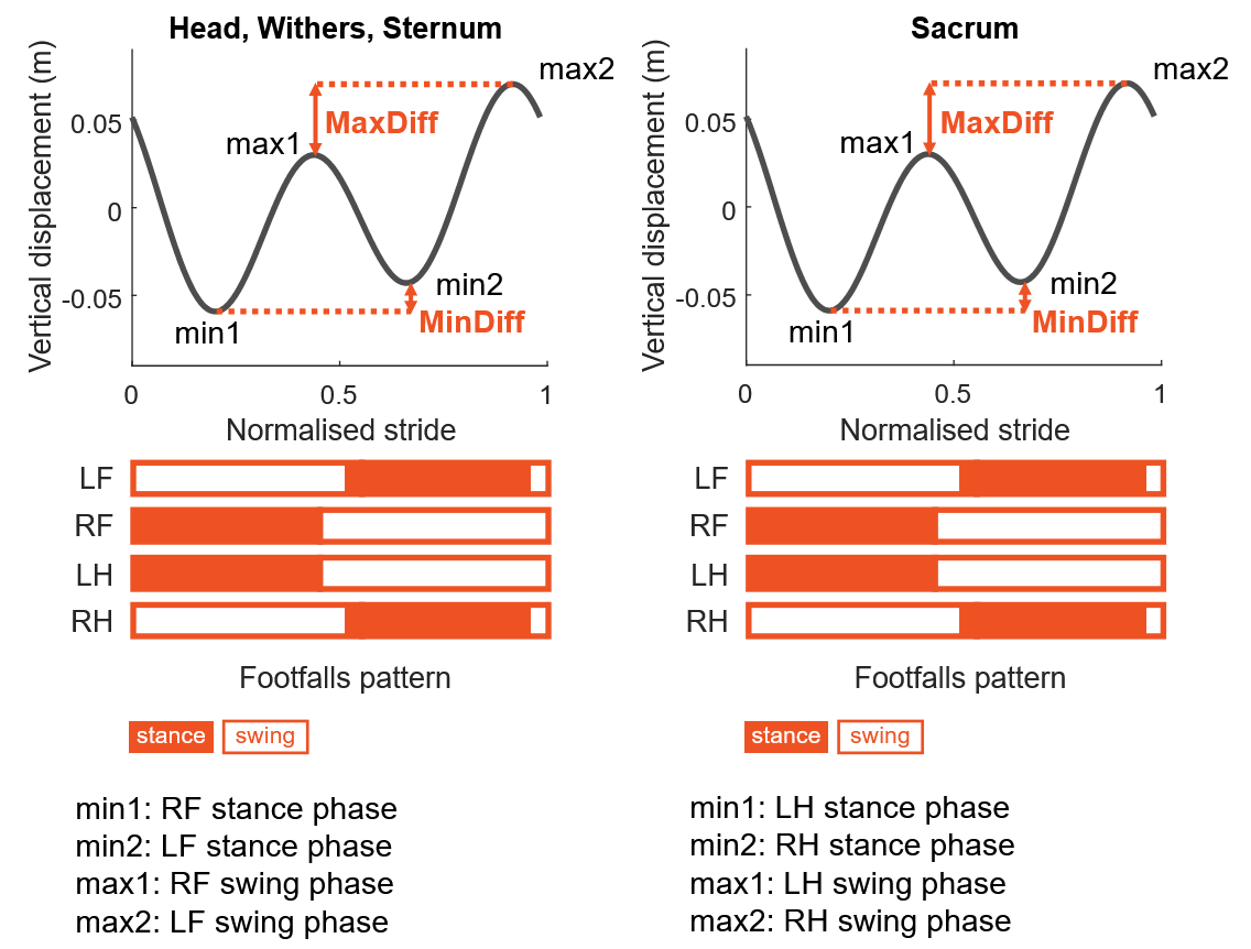
Figure 1 – Description of which time series events (min, max) are used to compute MinDiff and MaxDiff for the Head, Withers and Sternum (left) and for the Sacrum (right), the associated footfall patterns and the corresponding min/max events.
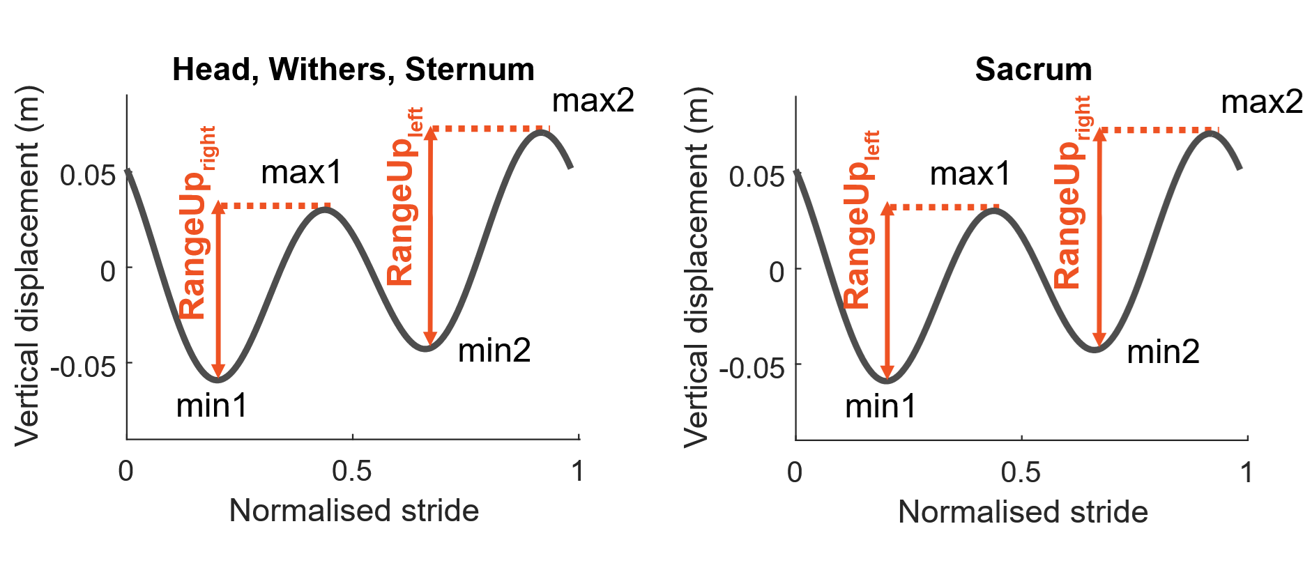
Figure 2 – Depicts the right and left RangeUp used to compute the Symmetry Index Up (SIUp) for the Head, Withers, Sternum (left) and Sacrum (right).
The equations for determining the described asymmetry parameters are given in Table 2.
Table 2: Equations of MinDiff, MaxDiff and Symmetry Index Up
| Parameter | Node | Equation |
| MinDiff | Head, Withers, Sternum | min1–min2 |
| MaxDiff | max2–max1 | |
| MinDiff | Sacrum | min2–min1 |
| MaxDiff | max1–max2 | |
| Symmetry Index Up (SIUp) | Head, Withers, Sternum, Sacrum | (RangeUpleft-RangeUpright)/max(RangeUpleft, RangeUpright) |
Asymmetry parameters for the hips (tubera coxae)
The asymmetry parameters for the hips are HipHike_swing and HipHike_stance are explained in the table below.
Table 3: Description of HipHike_swing and HipHike_stance
| Parameter | Node | Equation |
| HipHike_swing | Difference in vertical upwards displacement of the left and right tuber coxae during the hind limbs swing phase, in millimetre | Calculated at trot if tuber coxae sensors are available. Otherwise, rows are filled with “NaN”. |
| HipHike_stance | Difference in vertical upwards displacement of the left and right tuber coxae during the hind limbs stance phase, in millimetre | Calculated at trot if tuber coxae sensors are available. Otherwise, rows are filled with “NaN”. |
The figure below illustrates how these parameters are computed from the sensor data, in relation with the associated footfall patterns.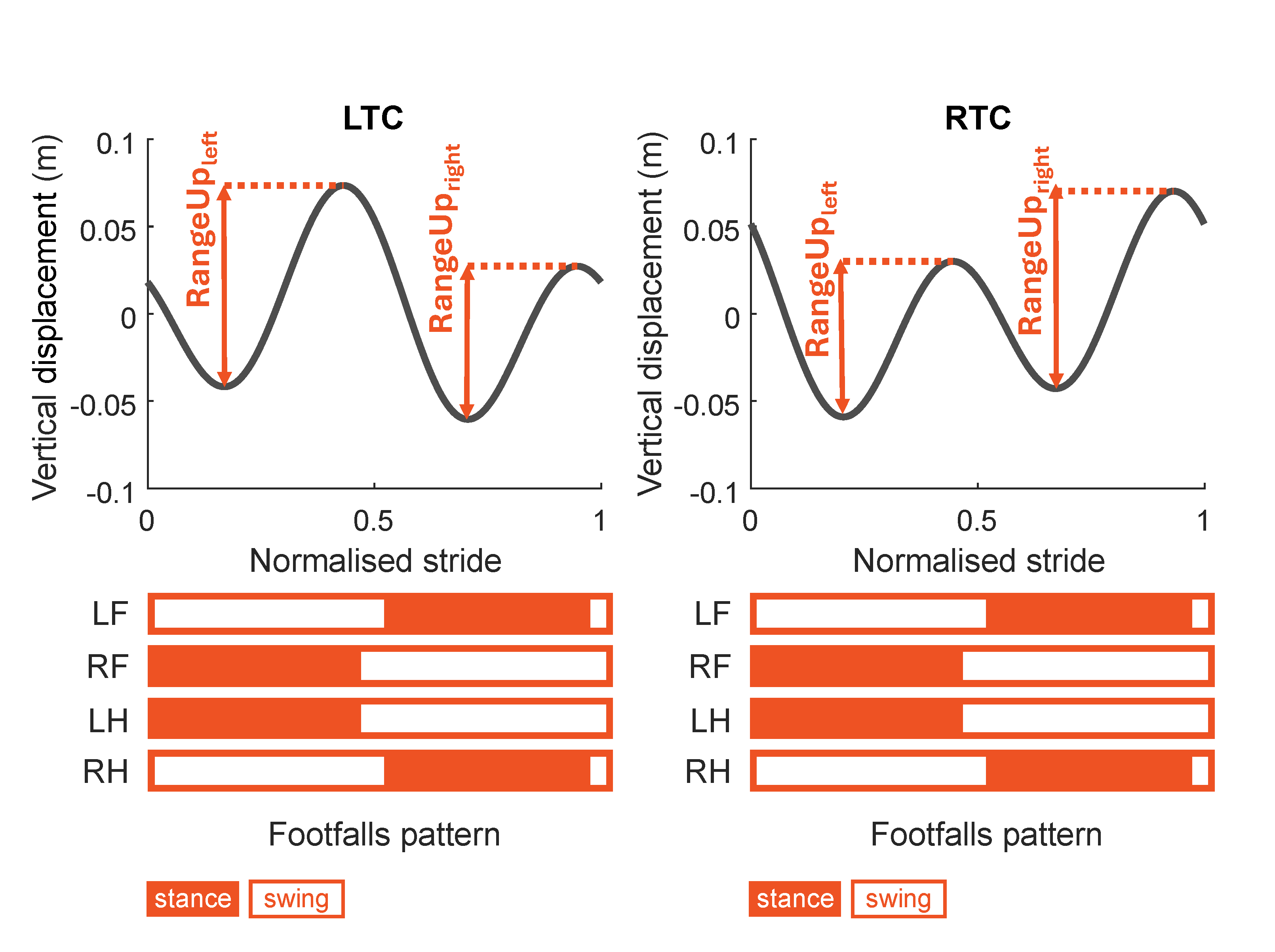
Figure 3 – Methods to calculate hip-related parameters available in Equi-Pro: the description of which timeseries events (RangeUp left and right) are used to compute HipHike_stance and HipHike_swing using the left tubera coxae (LTC) and right tubera coxae (RTC) nodes, and the associated footfall patterns.The equations for determining the hip-related asymmetry parameters are given in Table 4.
Table 4: Equations of HipHike_swing and HipHike_stance
| Parameter | Node | Equation |
| HipHike_swing | Combination of Left Tubera Coxae (LTC) and Right Tubera Coxae (RTC) | RTC(RangeUpleft)–LTC(RangeUpright) |
| HipHike_stance | Combination of Left Tubera Coxae (LTC) and Right Tubera Coxae (RTC) | LTC(RangeUpleft)– RTC(RangeUpright) |